Calculation of the electric field generated by systems of indefinite rectilinear conductors
Purpose
This tool allows you to determine the levels of
electric field dispersed by one or more bundles
(or systems) of indefinite rectilinear conductors,
all parallel to each other.
A model of this type is commonly used to
represent power lines, as also provided for by the CEI 211-4 guide
Guide to the methods of calculating electric and magnetic fields
generated by power lines and stations
, at least for the part
relating to two-dimensional models.
The tool is therefore useful to evaluate the exposure to the electric field of those who, for work or other reasons, must remain near power lines, in cases where a two-dimensional model allows you to obtain an accurate result. This occurs, in particular, in the presence of overhead lines, around which the conductors can be considered parallel to each other and to the ground surface, at least for a sufficiently long stretch with respect to the distances between the conductors themselves.
General setting
The application allows you to consider up to 10 bundles of conductors, each of which represents, in the most typical case, a three-phase power line; however, the general approach adopted makes the application very flexible, able to adapt to even very different situations.
Each conductor system is described through the starting data entered in a specific numbered sub-tab, located in the Data Entry tab. These data consist of the position of the conductors in space (specified by locating the point of intersection of the conductor with the calculation plane) and the values of the intensity and phase of the current on them.
The processing produces, in the Results tab, a summary with the peak value and the distance from the origin of the point where this is reached, and a table containing the distances from the origin at which a series of significant values are obtained (1, 2 and 5 V/m).
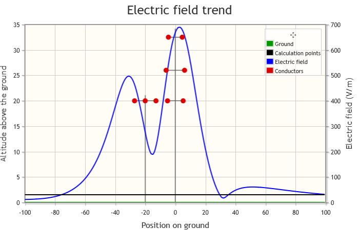
A graph is also displayed, showing the trend of the intensity of the electric field along a segment positioned on the calculation plane and parallel to the ground (see the following figure, click to enlarge).
Calculation details
Geometry of conductors
Conductors are considered to be cylindrical in shape, with a constant diameter and small compared to their mutual distances. Unlike the calculation procedure used in standard 211-4, in which at a certain point the one-dimensional conductors are considered, in this case the radius of the same is considered in all the passages.
Bundled conductors
In this case it is assumed that:
- the distance between subconductors of a phase is small compared to the distance between conductors at different potential;
- all the subconductors of a phase are equal to each other;
- in a normal section of the bundle the centers of the subconductors of a phase lie on a circumference.
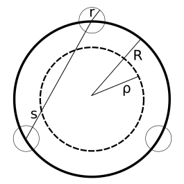
In the case of n conductors of radius r, arranged around a circumference of radius R, where s is the distance between adjacent subconductors, the equivalent radius ρ is used for the calculation:
Approximations
The presence of support pylons or pylons, buildings, vegetation and any other object in the area of interest is ignored.
The ground, flat and free of irregularities, is considered to be perfectly conductive, and is taken into account using the theory of image charges.

Calculation setup
In addition to the phase conductors, the guard cables are also considered (in light blue in the figure), placed at earth potential.
Data NC conductors, indicated with:
- V1, V2, ... V2NC le respective voltages (including images)
- λ1, λ2, ... λ2NC the charge densities;
- P1, P2, ... P2NC the positions of the conductors;
the electric field at a point Q is given by:
The voltage of the l-th conductor with respect to ground can be expressed as:
where:
- hk is the altitude above the ground of the k-th conductor;
- dkl is the distance from the center of the k-th conductor to the surface of the l-th conductor;
- dkk is the radius of the l-th conductor.
To determine the charge densities, it is necessary to solve a linear system of NC equations in NC unknowns (the densities λk) of this type.
In matrix form, this system can be expressed, indicating with [V(t)] and [λ(t)] the vectors of the voltages and the charge densities, as:
and the linear charge densities are obtained by inverting the matrix of the parameters:
having placed:
In particular, the i-th component of [λ(t)] is obtained, indicating with cik the element of [C], from:
where Vk and φk indicate respectively the voltage and phase of the k-th conductor, and the last equality is possible by virtue of the fact that the frequency of the signal is the same for all conductors.
Using phasors:
You get:
Once the charge densities have been obtained, they are used in the initial formula to determine the effective electric field. Remembering that the component parallel to the conductor is zero:
Limitations
The basic condition of the model, i.e. the validity of a two-dimensional representation of the problem, cannot be considered satisfied in close proximity to supports or intersections between two or more lines and, in general, in electrical stations.
Definition of structures
The tool allows you to define up to 10 conductor systems, i.e. overhead power lines, each consisting of 1 to 30 straight, horizontal, parallel to each other and to the ground and undefined conductors.
The voltage frequency must be the same in all conductors. The user must indicate whether this is three-phase alternating, single-phase alternating or direct. In any case, the voltage value associated with each conductor must be referred to earth; if the nominal voltage between 2 phases is known, it must be divided by sqrt(3), an operation that is performed automatically by selecting Three-phase alternating current and using a predefined support type present in the archive (see below).
For example, the voltages referred to the ground for typical values are:
- 76.210 kV for voltage between conductors equal to 132 kV
- 86.603 kV for voltage between conductors equal to 150 kV
- 127.017 kV for voltage between conductors equal to 220 kV
- 219.393 kV for voltage between conductors equal to 380 kV
If the user selects Single-phase alternating current or Continue, using the predefined pylon types the field relating to the voltage value must be populated manually.
To place the conductors in the space it is necessary to position their relative structure absolutely. To this end, it is necessary to specify:
- the altitude above the ground of the lowest conductor;
- the distance (measured along the ground, which may be inclined) of the foot of the perpendicular conducted for the origin of the internal reference system of the structure, from the origin of the absolute reference system (placed at ground level).
The following figures show the absolute (in black) and structural (in blue) reference systems in the cases of flat and inclined ground (click to enlarge):


Definition of conductors
Each conductor system is characterized
by a structure that documents its geometric characteristics,
with reference to the calculation plane (the vertical plane, orthogonal
to the direction of the conductors, on which the points are located
where the electric field will be calculated). We will call traces
the points where the
conductors intersect the calculation plane. The structure must be
designed with its own internal orthogonal Cartesian reference system
having:
- origin at a conventional point of the calculation plane, located vertically at the level of the track of the lowest conductor and horizontally along the axis of the support;
- horizontal X-axis directed towards the right;
- vertical Y-axis directed upwards.
The following figures show the internal reference system (in blue) for an asymmetrical pylon with three conductors and a symmetrical one with six (click to enlarge):


In addition to the altitude above the ground of the lowest conductor and the horizontal positioning, in the case of multiple subconductors it is necessary to indicate whether the geometric parameter reported for each conductor indicates the radius of the circumference around which the subconductors are arranged, or the distance between two of them.
For three voltage values (132 kV, 220 kV and 380 kV) the user can optionally select one of two predefined structures (single and double triplet respectively), chosen as the most impactful in their category from the point of view of the dispersed magnetic field. Alternatively, you can define your own custom structure, specifying the number of conductors and, for each of them:
- the coordinates of the suspension points, expressed in the internal reference system of the structure;
- the type of conductor (phase or guard wire);
- the voltage referred to earth;
- the phase;
- the radius;
- the number of sub-conductors;
- the radius of the circumference containing the sub-conductors, or the distance between two of them.
The data relating to a structure can be replicated in another, specifying its progressive number with the wording Replicate these parameters to structure no. ... and pressing the button with the green arrow.
Definition of the calculation points and the field value
Finally, the parameters needed to perform the
calculation of the electric field along a segment lying on the
calculation plane and parallel to the ground (hereinafter calculation
segment
) must be specified:
- slope of the ground
- initial distance (distance, measured along the ground, of the foot of the perpendicular drawn for the initial point of the calculation segment, from the origin - necessarily placed at ground level - of the absolute reference system)
- number of points into which to divide the calculation segment
- advancement step along the calculation segment
- constant height of the calculation segment on the ground
The results are shown in a graph; some summary data are summarized in tabular form.
Keywords: Calculation, Electric field, Indefinite rectilinear conductors