Comparison of magnetic flux density generated by systems of indefinite rectilinear conductors
Purpose
This tool allows you to compare the levels of magnetic flux density generated by bundles of undefined rectilinear conductors (or systems), parallel to each other and to the ground.
General setup
The application allows you to consider up to 10 conductor bundles. Unlike the application Calculation of the magnetic flux density generated by multiple systems of indefinite rectilinear conductors, where the calculation considers the overall contribution of all the conductors, here it is performed separately for each system. This allows us to compare the maximum level and spatial distribution of the magnetic induction generated by each of them.
Each system is described through the initial data entered in a specific numbered sub-tab, located in the Data Entry tab. This consists of the position of the conductors in space (specified by locating the intersection point of the conductor with the calculation plane) and the values of the current intensity and phase on them.
The processing produces, in the Results tab, a numbered sub-tab for each conductor system; this reports the corresponding peak value and the distance from the origin of the point at which it is reached, and a table containing the distances from the origin at which a series of significant values are obtained (0.4, 3, 10, and 100 µT).
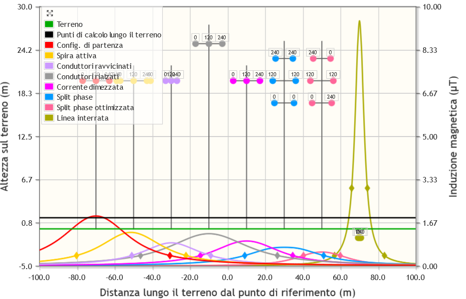
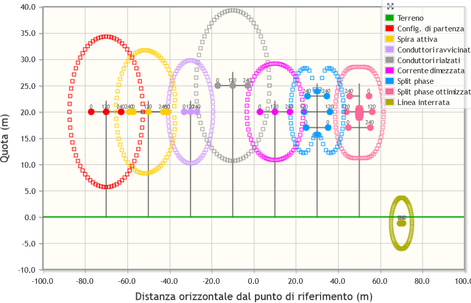
Two plots are also displayed, showing the trend of the magnetic induction intensity along a segment positioned on the calculation plane and parallel to the ground and the set of points where the flux density reaches a value preset by the user. Each graph displays the calculated quantities for all the defined structures, allowing them to be compared (see the following figures, click to enlarge).
Limitations
The geometric representation of the problem and consequently the processing of the results are based on a two-dimensional model of the conductor systems (see CEI 211-4 guide Guide to the methods of calculation of electric and magnetic fields generated by power lines and substations).
Definition of structures
The tool allows you to define up to 10 conductor systems, i.e., overhead or underground power lines, each consisting of 1 to 30 straight, horizontal, parallel conductors to each other and to the ground, and infinite.
To place them in space, you need to absolutely position the related structure. To this end, you need to specify:
- the height above the ground of the lowest conductor;
- The distance (measured along the ground, which may be inclined) of the foot of the perpendicular drawn through the origin of the structure's internal reference system, from the origin of the absolute reference system (placed at ground level).
The following images show the absolute (in black) and structural (in blue) reference systems for flat and inclined terrain (click to enlarge):


Definition of conductors
Each conductor system is characterized by a structure that
documents its geometric characteristics, with reference to the
calculation plane (the vertical plane, orthogonal to the direction
of the conductors, on which the points where the magnetic field will be
calculated are located). We will call the points where the conductors
intersect the calculation plane tracks
. The structure must be
designed with its own internal orthogonal Cartesian reference system
having:
- origin at a conventional point on the calculation plane, located vertically at the level of the track of the lowest conductor and horizontally along the axis of the support, in the case of an overhead line, or approximately at the center of the tracks of the conductors, in the case of an underground line;
- horizontal X-axis pointing to the right;
- vertical Y-axis pointing upwards.
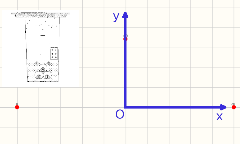
The following images show the internal reference system (in blue) for an underground power line, an asymmetrical pylon with three conductors and a symmetrical one with six (click to enlarge):


For three voltage levels (132 kV, 220 kV, and 380 kV), the user can optionally select one of four predefined structures (single and double circuit, overhead or underground, respectively), chosen as the most impactful in their category in terms of stray magnetic field. Alternatively, the user can define their own custom structure, specifying the number of conductors and, for each:
- the coordinates of the suspension points, expressed in the structure's internal reference system;
- the current value and its phase.
The data relating to one structure can be replicated in another by specifying the sequence under Replicate these parameters to structure no. ... and pressing the green arrow button. This can be useful if you want to determine the variation in induction as a function of some of the parameters (e.g., the current or the height from the ground of the lowest conductor, leaving the geometry of the support unchanged).
Defining the calculation points and the field value
Finally, the parameters needed to calculate the magnetic flux density
along a segment lying on the calculation plane and parallel to the ground
(hereinafter calculation segment
) must be specified:
- ground slope
- initial distance (distance, measured along the ground, of the base of the perpendicular drawn through the starting point of the calculation segment, from the origin - which must be at ground level - of the absolute reference system)
- number of points into which to divide the calculation segment
- advancement step along the calculation segment
- constant height of the calculation segment above the ground
and around the conductors (isohypses at the required induction level):
- angular step
- desired magnetic flux density value.
The results are presented in two graphs; some summary data are presented in a table.
Examples
Keywords: Comparison, Magnetic flux density, Calculation, Indefinite rectilinear conductors