Calculating the magnetic flux density generated by multiple helical conductor systems
Purpose
This tool allows you to determine the levels of magnetic flux density dispersed by one or more bundles (or systems) of helicoidal conductors(1), whose helix axes are all parallel to each other and to the ground.
The tool is therefore useful for assessing the magnetic field exposure of those who, for work or other reasons, must remain near underground power lines with spiral conductors.
General setting
The application considers up to 10 conductor systems, each of which represents, in the most typical case, a three-phase underground power line with helicoidal conductors.
The initial data essentially consist of the position of the conductors in space (specified through the localization of the intersection point of the conductor's helix axis with the calculation plane) and the values of the current intensity and phase on them.
The processing produces, in the Results tab, a summary with the peak value and the distance from the origin of the point where it is reached, and a table containing the distances from the origin at which a series of significant values are obtained (0.4, 3, 10, and 100 µT).
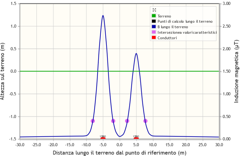
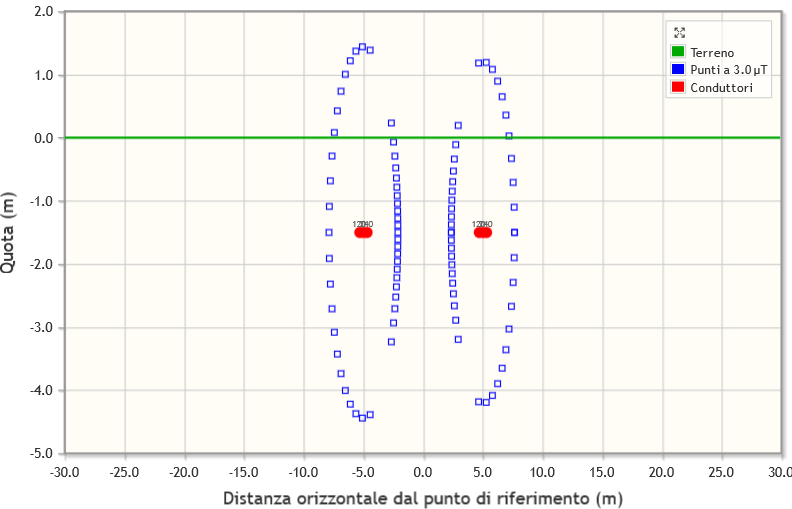
Two graphs are also displayed, showing respectively the trend of the magnetic flux density along a segment positioned on the calculation plane and parallel to the ground and the locus of the points where the induction itself reaches a value preset by the user (see following figures, click to enlarge).
Model
The application uses a mixed two- and three-dimensional model. The locus
of points where the magnetic flux induction will be calculated
necessarily lies on a vertical plane, called the calculation plane
,
orthogonal to the direction of the axes of the conductor helices. The
latter are modeled through the sum of many elementary segments that
follow the conductor's spiral in 3D space for a section upstream and
downstream of the calculation plane.
(1) A helical conductor means a conductor wound in a helix around an axis that we will consider straight and horizontal.
[See also the methodological approach graph]
Definition of structures
The tool allows you to define up to 10 conductor systems, i.e., buried power lines, all parallel to each other. Each can be made up of 1 to 30 helicoided conductors, in which the axes of the helices are all parallel to each other, and characterized by some common parameters:
- length of the helix pitch;
- number of complete helix cycles (which are understood to be distributed half upstream and half downstream of the plane on which the points where thefield is calculated are located);
- number of segments per pitch.
Definition of conductors
Each system of conductors is characterized by a geometric structure
for which the following must be defined:
- Number of conductors
- an internal orthogonal Cartesian reference system, with a horizontal X
axis pointing to the right and a vertical Y axis pointing upward, for
which the following must be specified:
- Position along the ground
- Depth of burial
And for each conductor:
- Coordinates with respect to the center
- Current and phase values
Data relating to one structure can be replicated in another, by specifying the sequence number under Replicate these parameters to structure no. ... and pressing the green arrow button.
Definition of the calculation points and the field value
Finally, the parameters needed to calculate the magnetic induction along
a segment lying on the calculation plane and parallel to the ground
(hereinafter calculation segment
) must be specified:
- ground slope
- initial distance (distance, measured along the ground, of the base of the perpendicular drawn through the starting point of the calculation segment, from the origin - which must be at ground level - of the absolute reference system)
- number of points into which to divide the calculation segment
- advancement step along the calculation segment
- constant height of the calculation segment above the ground
and around the conductors (isolines at the required induction level):
- angular step
- desired magnetic flux density value.
The results are shown in two graphs; some summary data are presented in tabular form.
Keywords: Calculation, Magnetic flux density, Helical conductors