Electromagnetic Compatiblity
Electromagnetic compatibility (EMC) tests take place in a controlled environment (anechoic chamber) such as to appropriately attenuate both the background coming from the outside and the echoes generated on the walls of the chamber from the radiation emitted by the equipment inside.
The anechoic chamber is essentially formed by an external casing made of aluminum, for shielding the electromagnetic radiation coming from the outside, and an internal casing (floor, ceiling and walls) composed of ferromagnetic tiles for internal radiation absorption and attenuation of echoes. The echoes attenuation at high frequencies (> 1 GHz) typically requires the installation of bulky ferromagnetic panels with shapes of suitable geometry (pyramids) and allows the effectiveness of the attenuation to be extended to higher orders of frequency.
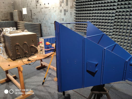
Typical set-up for radiated susceptibility or emission test with double ridged horn antenna, 200 MHz - 2 GHz band.
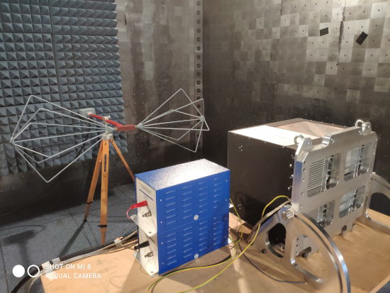
Typical set-up for radiated susceptibility test with biconical antenna, 30 MHz - 200 MHz band.
The instrumentation used to carry out EMC checks consists of signal generators, amplifiers, antennas, current injection probes, coupling transformers, LISN, oscilloscopes, signal and spectrum analyzers, electric or magnetic field meters, compatible with the frequency spectrum and signal intensity characteristic of the single measurement.
EMC checks are of two types:
- on the electromagnetic emission produced by the electronic system under study (equipment under test, EUT) and measured by appropriate calibrated instrumentation, in order to measure emitted radiation levels and, if required, to verify the compatibility with the maximum levels permitted in the environment where the system will operate (for example, on board of a satellite).
- on the susceptibility of the electronic system under observation (EUT), with respect to external electromagnetic interference injected into the system using appropriate calibrated instrumentation: the test allows to verify the correctness of functionality and performance of the system in the presence of these external stimuli. If required, stimulus levels are defined accordingly to those expected in the environment in which the system will operate.
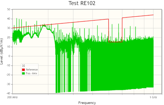
Example of measured radiated emission spectrum, with reference limit.
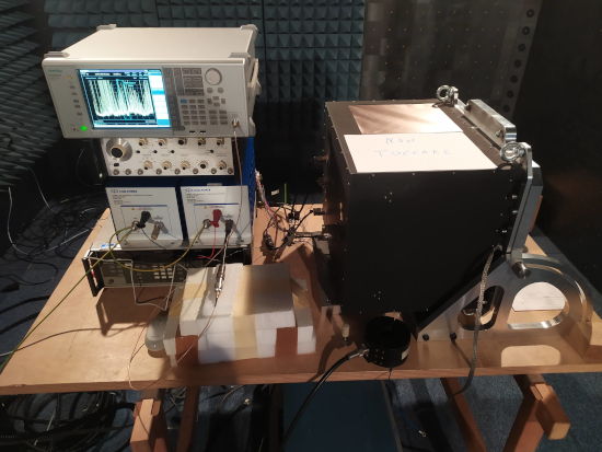
Typical set-up for test of conducted emission on power lines with LISN, 150 kHz - 10 MHz band.
The checks are traditionally divided into conducted and radiated. In the conducted case, the measurement is carried out by taking/injecting the signal (via capacitive or inductive couplings) directly on the power supply cables or analog/digital interfaces connecting EUT on the outside. In the radiated case, the measurement is carried out by taking/injecting the signal via an antenna located near the EUT.
The checks (both emission and susceptibility) may concern impulsive and transient temporal profiles, which reproduce the electromagnetic emissions following switching on, off or changing configuration of an apparatus. Or they may concern continuous electromagnetic emissions, as they occur during regular operation of an apparatus, which are characterized as a function of frequency, by scanning in a given frequency range with signal collection in each defined band for a defined time.
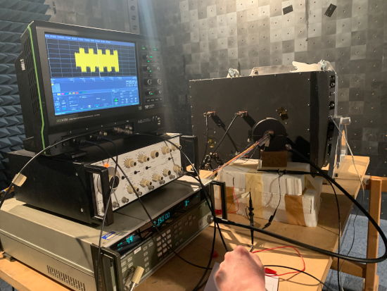
Typical set-up for conducted susceptibility test with current injection probe, 10 kHz - 200 MHz band.
Some common types of emission checks are as follows.
- Measurement of the interference voltage injected by the EUT on the power supply lines, in the 100 kHz - 10 MHz band. This emission is primarily due to the voltage regulation circuits on board the EUT. The interference signal is picked up on the line via controlled impedance filter (LISN) and measured by spectrum analyzer.
- Measurement of environmental electric field emission, in the 100 MHz - 1 GHz band. This emission is generally due to all active circuits during operation of the EUT. The interference signal is measured via antenna and spectrum analyzer.
Some common types of susceptibility tests are as follows.
- Verification of the susceptibility of the EUT to sinusoidal interference injected onto the power cables, in the 30 Hz - 150 kHz band with the desired spetral intensity. The interference signal is injected through a coupling transformer.
- Verification of the susceptibility of the EUT to sinusoidal interference (with pulse modulation) injected onto the power and signal cables, in the 10 kHz - 200 MHz band with the desired spectral intensity. The interference signal is injected via a current injection probe.
- Verification of the susceptibility of the EUT to sinusoidal electric field interference (with pulse modulation) generated via antenna, in the 10 kHz - 40 GHz band with the desired spectral intensity.
Keywords: EMF, Electromagnetic Fields, Electromagnetic Compatiblity